
Connectivity at different layers
Have you ever looked at your machines and thought to yourself: Great, I have this machines. But I really can’t get them to talk to each other the way I want them to. No? Just me? Alright, maybe it’s just me then but I bet many of you have faced similar challenges when trying to establish connectivity between different systems, services, or applications. Because here’s the thing: connectivity is a fundamental aspect of modern computing, and understanding how it works at different layers can make a huge difference in troubleshooting and optimizing your network. Sometimes, it’s not just about plugging in cables or configuring IP addresses; it’s about grasping the underlying principles that govern how data flows through networks because you don’t always have control over all aspects of a network: Some examples of this can be found in cloud environments, complex enterprise setups or using some form of service that might probably require an specific configuration. That’s ok, is just how it is. Sometimes you don’t have control over everything, but understanding can help you navigate those limitations.
Now, you might be thinking:
Oh no, not another networking tutorial!, I hate this, bad reviews, bye-bye you loser
Well. Leave if you want, I won’t stop you. But if you stay, I promise it will be worth your time because this post is designed to be a quick and easy guide to understanding connectivity at different layers of the OSI model. You don’t have to be a networking expert to understand these concepts: whether you’re a beginner or just need a refresher, this tutorial will grasp the essentials without overwhelming you with technical jargon and that kind of stuff.
The OSI Model: A Quick Overview
I know I promised “no jargon” and then immediately walked in carrying the Open Systems Interconnection (OSI) model like a shiny nerd trophy. But it really helps: OSI is a reference model: great for thinking and troubleshooting, while real-world stacks do not map perfectly to it. Think of OSI as a debugging lens, not a law of physics. Now enough with the fancy talk, let’s try to explain this like it’s a space mission:
Layer 1: Physical Layer
Ok so we have our space mission. Mission control cannot talk to the spacecraft unless something can carry the signal. That “something” is Layer 1: cables, fiber, radios, antennas, optics, transceivers… the “physical signaling” layer. Layer 1 is responsible for the physical connection between devices, transmitting raw bits over a physical medium. In our space mission analogy, this layer would be the antennas and transmitters that allow mission control to send signals to the spacecraft, spacecraft to receive them and also any communication from spacecraft to mission control.
Possible situations (Layer 1)
- Damaged cables or faulty hardware can disrupt communication.
- Interference in the physical medium can affect transmission.
- Medium (Or the actual devices) limitations can restrict data transfer rates.
Possible solutions (Layer 1)
- Confirm physical connections.
- Regular maintenance and testing of physical components.
- Some physical layers support Forward Error Correction (FEC); when available, enabling it can improve resilience.
- Upgrading to higher-quality cables or devices to improve performance.
Layer 2: Data Link Layer
Ok, we have a physical connection now. But, what data are we going to send over that connection? This is where the Data Link Layer comes into play: It is responsible for establishing a reliable link between two directly connected nodes, handling error detection and correction, and managing access to the physical medium. In our space mission analogy, this layer would ensure that the data frames sent from mission control are correctly received by the spacecraft, and vice versa. Think of it like the spacecraft and mission control agreeing on how to package and validate the messages sent over the radio hop.
Possible situations (Layer 2)
- Data frames may get corrupted during transmission.
- Collisions can occur when multiple devices try to send data simultaneously (Usually not the problem with modern devices).
- Links not correctly established (VLAN mismatch, WI-FI problems, MAC problems, ARP issues, etc.).
- Addressing issues can arise when devices are not properly identified.
Possible solutions (Layer 2)
- Implementing error detection and correction mechanisms.
- Using protocols like CSMA/CD to manage access to the medium (If connection needs it).
- Establishing proper links to ensure reliable communication.
- Ensuring proper addressing schemes are in place.
Layer 3: Network Layer
Now that we have a reliable link between two nodes, we have a situation. What if I want to send data from mission control to the spacecraft, but there are multiple hops in between? This is where the Network Layer comes into play: It is responsible for routing data packets from the source to the destination across multiple networks. In our space mission analogy, this layer would ensure that the data packets sent from mission control are correctly routed through various relay stations and satellites to reach the spacecraft.
Possible situations (Layer 3)
- Routing issues can lead to data being sent to the wrong destination or no destination at all.
- Network congestion can cause delays in data transmission.
- IP address conflicts can disrupt communication.
Possible solutions (Layer 3)
- Implementing robust routing protocols to ensure data reaches the correct destination.
- Using Quality of Service (QoS) mechanisms to manage traffic queues.
- Ensuring proper IP address management to avoid conflicts.
Layer 4: Transport Layer
Now, we need to ensure that our data is actually sent. This is where the Transport Layer comes into play: It is responsible for end-to-end communication, ensuring that data is sent (And hopefully delivered). In our space mission analogy, this layer would ensure that messages from mission control are received by the spacecraft in the correct order and without any missing information. Think of it like the way spacecraft’s control systems (applications) receive orders and data from mission control.
Possible situations (Layer 4)
- Data packets may get lost or arrive out of order.
- Connection issues can lead to interruptions in data transmission.
- Flow control problems can cause data to be sent too quickly for the receiver to handle.
Possible solutions (Layer 4)
- Implementing reliable transport protocols like TCP to ensure data integrity.
- Using connection management techniques to maintain stable connections.
- Implementing flow control mechanisms to regulate data transmission rates.
Layers 5, 6, 7: Session, Presentation, Application Layers
Finally, we need to ensure that the data being sent is meaningful and can be understood by the receiving application. This is where the Session, Presentation, and Application layers come into play: They are responsible for establishing, managing, and terminating sessions between applications, ensuring that data is properly formatted and presented, and providing services directly to the end-user applications. In our space mission analogy, these layers would ensure that the messages from mission control are properly formatted and understood by the spacecraft’s systems.
Possible situations (Layers 5, 6, 7)
- Session management issues can lead to dropped connections.
- Data format incompatibilities can cause misinterpretation of information.
- Application-level errors can disrupt communication.
Possible solutions (Layers 5, 6, 7)
- Implementing robust session management protocols to maintain connections.
- Using standardized data formats to ensure compatibility.
- Ensuring proper error handling at the application level.
Conclusion (OSI Model)
See? It wasn’t that bad after all. Understanding connectivity at different layers of the OSI model can help you troubleshoot and optimize your network more effectively. By recognizing the specific challenges and solutions associated with each layer, you can better navigate the complexities of modern networking. When connectivity fails, guessing can be really expensive. The OSI model gives you a method: start low, move up, and avoid fighting the wrong layer. Most “network problems” are really “a single missing route”, “a blocked port” or “a single certificate that expired quietly in the night.”
Real-World Applications
Ok, so now that we have a basic understanding of the OSI model and connectivity at different layers, here is how it tends to show up in systems people actually run:
Cloud Computing
In cloud environments, connectivity is crucial for accessing resources and services. Understanding how data flows through different layers can help optimize performance and troubleshoot issues. For example, if you’re experiencing latency when accessing a cloud service, you might need to investigate the network layer for routing issues or the transport layer for connection problems. You might not have control over all layers, but understanding them can help you work within the constraints of the cloud provider’s infrastructure (And also help you communicate better with their support teams). Take for example “Access control lists (ACLs)” that are often used in cloud environments to restrict traffic at different layers, such as network and transport layers:
- VM1 cannot reach VM2 because there is no route (Missing Layer 3 connectivity: VPC/VNet route, broken peering, wrong subnet, no NAT, etc.).
- VM1 can reach VM2’s IP, but port 80/443 is blocked (Missing Layer 4 connectivity: security group / firewall rule / NACL (Network Access Control List), etc.).
A key clarification that saves time: in most clouds, things like Security Groups and Network ACLs are best understood as Layer 3/Layer 4 filtering (IP/ports/protocols). Usually, they do not “affect Layer 1 or Layer 2”, in a way those layers are provider territory.
Microservices Architecture
Microservices are networking-heavy by design: lots of small conversations instead of a few big ones. That means you will see failures at multiple layers, often at once. For example, if a microservice is unable to communicate with another service, you might need to investigate the transport layer for connection issues or the application layer for service-specific problems. In this case, you might find that:
- The service discovery mechanism is not functioning properly (Layer 7)
- TLS issues (Often described as ‘between Layer 4 and Layer 7’ depending on the model. Practically, it’s an application-stack concern that can make a healthy network look dead).
- The API endpoints are not reachable due to network misconfigurations (Layer 3)
Internet of Things (IoT)
In IoT environments, devices often communicate over wireless networks. The thing is that for troubleshooting purposes, you need to understand how connectivity works at different layers. For example, if an IoT device is unable to send data to a central server, you might need to investigate the physical layer for signal issues or the data link layer for connection problems. But you can also find IP-related problems (Layer 3) or even application-layer issues (Layer 7) depending on the specific scenario. For example:
- The device is out of range or drowned in interference (Layer 1).
- Wi-Fi association/auth fails, or the wrong SSID/VLAN is used (Layer 2).
- The device has an IP but cannot reach the broker/hub (Layer 3).
- Timeouts kill long-lived sessions and new ones can’t be established (Layer 4).
- Certificates expire on devices nobody patches (Layers 4+).
Connectivity tutorial
Now, there’s a pretty common use-case: Accessing private services (Or services behind some kind of firewall: Like databases, private APIs, internal VMs, etc.) by a public entity (Or one that has no direct access to the private service: Like a CI Runner, Central manager, etc.). This is a pretty common scenario because sometimes you need to access resources that are not publicly available, such as databases, internal applications, or private APIs from public machines but keep those resources as private. There’s lots of ways to achieve this:
Back to space: the spacecraft (private) cannot be directly dialed by mission control (public). So we build a relay plan:
- Layer 1: Is there any usable physical medium at all? (Antennas, transmitters, etc). Let’s assume yes. Check ✅
- Layer 2: Can the local link exchange data reliably? (Control to access physical connectivity). Again, assume yes. Check ✅
- Layer 3: Is there a route from mission control to the spacecraft? (Routing). Here we have a problem because the spacecraft is not publicly accessible. So we need to find a way to route the communication . As per the description probably there isn’t any route for this, one way of solving this is by using a relay satellite (Bastion host, VPN, etc) that both mission control and the spacecraft can communicate with.
- Layer 4: Can a connection be established? (Ports, protocols, etc). Assuming we have a route now, we need to ensure that the correct ports and protocols are being used. As stated earlier, mission control can’t initiate communication with the spacecraft, so if inbound connections are blocked but outbound is allowed, flip the direction: have the private side initiate (reverse tunnel, agent-based connection, etc.). This way, the spacecraft can establish a connection to mission control through the relay satellite, allowing for two-way communication.
- Layers 5, 6, 7: Is the data meaningful? (Sessions, formatting, applications, etc). Finally, we need to ensure that the data being sent is properly formatted and understood by both parties. Assuming the previous layers are functioning correctly, we can focus on ensuring that the messages are correctly formatted and that both mission control and the spacecraft can interpret them. This is not relevant to our problem really because it was stated that machines can’t communicate as they should so the data being sent is not meaningful (At least not right now).
So how do we solve the Layer 3/4 parts in real life? You have options. Some are mostly Layer 3 (routing: Like VPNs), some are mostly Layer 4 (TCP relays), and some are Layer 7 (HTTP reverse proxies). Real networks do not respect clean layer boundaries, and that is fine. I’m going to give five easy examples of how you would solve the identified problems:
- Using a Bastion Host (Jump box): Set up a bastion host (relay satellite) that both the public machine (mission control) and the private resource (spacecraft) can communicate to. This allows the public machine to communicate with the private one using this intermediary. This is simple, auditable, and boring (Sometimes boring is good), it is also interactive by default, which may or may not be what you want.
- Using a Virtual Private Network (VPN): Establish a VPN connection between the public machine and the private network where the resource resides. By creating a secure tunnel, the public machine can access the private resource as if it were on the same local network (In other words, create a network for this two to communicate).
- Using SSH Tunneling: If the private resource allows outbound SSH connections, you can set up an SSH tunnel from the public machine to the private resource through an intermediary server (relay satellite). This allows the public machine to forward traffic to the private resource securely.
- Using a Layer 7 Proxy: A Layer 7 proxy is an intermediary server (relay satellite) that can understand application-wide protocols like for example HTTP/HTTPS . This is useful when you want to “limit” the usage to just an specofic application, for example: for security this means that you can block certain traffic based on application-wide requests.
- Using a Layer 4 Proxy: A Layer 4 proxy is an intermediary server (relay satellite) that doesn’t understand application-wide protocols like HTTP/HTTPS but only transport-wide protocols like TCP or UDP. This gives you more possibilities as to what traffic can be sent using this proxy but you can’t establish application-wide configurations.
Ok I did that on purpose. What? Using a generic definition for proxies. Why? Probably you’ve heard that there’s Forward and Reverse proxies, I just wanted you to know that the core idea is the same: a middlebox relays traffic between two parties. Yes, there are different implementations and that kind of stuff, but the idea is the same.
Forward proxies are client-side (Meant to represent the client: Sometimes explicitly configured, sometimes enforced transparently. This relates to egress traffic: Traffic leaving a client environment/network).
Reverse proxies are server-side (Meant to represent the server: Clients may or may not realize a proxy is involved. This relates to ingress traffic: Traffic entering a server environment/network).
Enough talking, let’s do some practical examples:
- Bastion host example:
| |
Here we are using the -J flag to specify the bastion host as a jump host to connect to the private resource.
- VPN example:
Setting up a VPN can vary depending on the software used, but here’s a basic (Unsafe) example using OpenVPN:
| |
| |
Here we are starting the OpenVPN server and connecting to it from the public machine. Once connected, traffic gets routed over the tunnel. If you need the client to reach private subnets behind the VPN server, you add routes and enable some kind of forwarding.
- SSH Tunneling example:
| |
Here we are forwarding local port 8080 on the public machine to port 80 on the private resource through the bastion host. So any data sent to localhost:8080 on the public machine will be forwarded to the private resource. If we want the private resource to initiate the connection instead, we can use reverse tunneling.
| |
Here we are forwarding port 80 on the private resource to port 8080 on the bastion host. So any data sent to bastion_host:8080 will be forwarded to port 80 on the private resource.
| |
Here we are setting up a dynamic port forwarding (SOCKS proxy) on port 1080 on the public machine. This allows us to route traffic through the bastion host to the private resource. Note that in this case the tunnel is not static, we can connect to any port on the private resource that the proxy can reach by configuring our applications to use the SOCKS proxy.
By default, remote forwards may bind to 127.0.0.1. Exposing them publicly requires SSH server configuration (GatewayPorts) and firewall rules. This is usually a feature, not a bug.
- Layer 7 Proxy example:
A Layer 7 (Application) proxy understands an application protocols (most commonly HTTP/HTTPS). Because it understands HTTP, it can do things like routing based on host/path, authentication, header manipulation, and TLS termination.
4.1 Layer 7 Forward proxy example (client-side)
A forward proxy represents the client. The client (or the network) sends outbound HTTP requests to the proxy, and the proxy makes the requests to the destination server on the client’s behalf.
Example
- Client is configured to use forward proxy at the relay satellite
- Client requests http://private_resource:80
- Proxy fetches it and returns the response
4.2 Layer 7 Reverse proxy example (server-side)
A reverse proxy represents the server. Clients connect to the proxy as the public “front door,” and the proxy forwards requests to private backends (optionally load balancing between many). Clients generally do not need special proxy configuration.
| |
Here we are configuring Nginx to listen for application traffic on port 80 and forward requests to the private resource. The public machine can then access the private resource by sending requests to the bastion host (But only HTTP not any arbitrary protocols. This is important to understand).
- Layer 4 Proxy example:
A Layer 4 proxy forwards connections based on IP:port and connection state, it’s more frequently used with connection-oriented protocols (Like TCP). It does not understand application semantics, which is why it works for many TCP-based protocols (databases, SSH, custom TCP services).
5.1 Layer 4 Forward proxy example (client-side)
A Layer 4 forward proxy represents the client. The client connects to the proxy and asks it to send traffic to a destination host:port.
Example
- Mission control uses SOCKS5 proxy at relay satellite
- Mission control asks: “connect me to private_resource:5432”
- Proxy opens the TCP connection and relays bytes
5.2 Layer 4 Reverse proxy (server-side)
A Layer 4 reverse proxy represents the server. Clients connect to a stable public IP:port, and the proxy forwards the TCP stream to another backend host:port (optionally load-balancing among multiple backends).
| |
Here we are configuring Nginx to listen for TCP traffic on port 15432 and forward requests to the private resource. The public machine can then access the private resource by sending requests to the bastion host (It can be any arbitrary protocols. This is important to understand).
Practical exercise
Now, I could end up this tutorial here, but I think it would be more fun if we actually try to implement one of these solutions. So here’s a practical exercise we’ll be doing together:
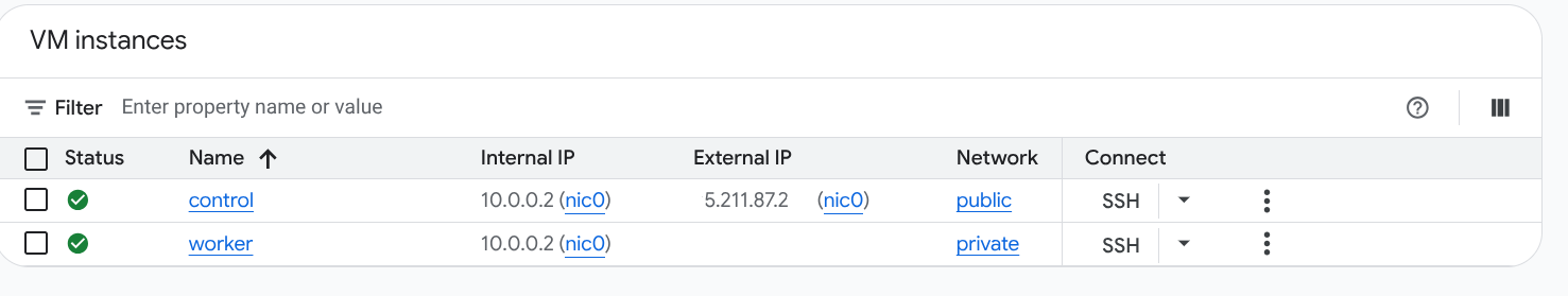
I want to set a Kubernetes cluster with two nodes:
- Node 1: Public node (Mission control: Control plane)
- Node 2: Private node (Spacecraft: Private resource –> Can’t be accessed directly from Node 1)
The goal is to run a cluster where the control plane is reachable, but a worker node is private. For this we’ll use Konnektivity, now, Why this not so common tool? Because it’s easy to set up and use, it abstracts away a lot of the complexity involved in setting up connectivity between public and private nodes, plus, it works really well with Kubernetes, which is what we’re aiming for here. Why not a more traditional thing? Like a VPN Good question, I hope my answer satisfies you: Because setting up a VPN, can sometimes be an overkill (Like in this case where all we need is to connect to the private node’s Kubelet to the public machine) and if not configured correctly, potentially insecure. With Konnektivity, we’re able to establish connectivity at Layer 4 without the need for connecting different networks, making it simpler and more efficient for our needs.
So, let’s get started with the practical exercise:
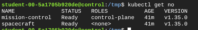
- Set up a Kubernetes cluster with one public control plane node and one private worker node.
- Install and configure Konnectivity on both nodes to establish connectivity between them.
- Verify that the control plane can communicate with the private worker node using Konnectivity.
- Deploy a sample application on the private worker node and access it from the control plane.
- To set up the Kubernetes cluster, you can use tools like
kubeadm,k3s, ormicrok8s. For this exercise, I usedkubeadmfor a more traditional approach. Make sure you have two machines (or VMs) ready: one for the control plane and one for the worker node, and that they are properly configured with the necessary network settings so that worker node cannot be accessed directly from the control plane but the worker node can reach the control plane. To simulate this, you can set up firewall rules or configure your network for this (I created some Cloud VMs on different networks with no private connectivity and only one with public IP that the “work machine” could reach because I didn’t want to mess up my network).
This is not a Kubernetes tutorial, so I won’t go into the details of setting up the cluster, but you can find plenty of resources online for that. For this specific case, you need a cluster with one control plane node and one worker node.
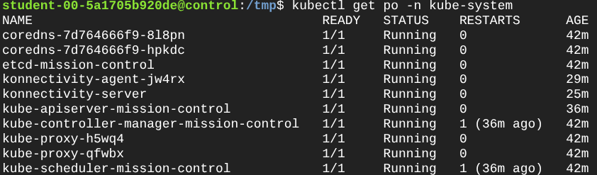
- Here comes one of my favorite parts: Installing and configuring Konnectivity. First, we need to install the Konnectivity server on the control plane node and the Konnectivity agent on the worker node. You can find the installation instructions in the Kubernetes documentation. Just know that in this tutorial, the agent gets installed as part of a Daemon Set on the worker node, so it can run on various nodes (e.g., multiple worker nodes).
The documentation is pretty good, so I won’t repeat it here, but make sure to follow the steps carefully and more importantly: understand what you’re doing. The key part is to configure the API server to use Konnectivity for egress traffic, setup the Konnectivity server in the control plane and make sure that the agent connects to this proxy.
- Now, let’s verify that the control plane can communicate with the private worker node using Konnectivity. You can do this by checking the logs of the Konnectivity agent on the worker node and ensuring that it is successfully connected to the Konnectivity server on the control plane. You can also try to access the Kubelet API on the worker node from the control plane using
kubectlcommands.

- Finally, let’s deploy a sample application on the private worker node and access it from the control plane. You can use a simple Nginx pod for this. I ran a pod using the CLI like this:
| |

Great so, to finish I just went ahead and tried executing a command inside this pod. Why? Why not just accessing the default page? Well, I believe that’s out of the scope for this tutorial but the Kubelet really is the component that is in charge of managing the containers on each pod and providing the APIs that the API Server uses, so if the API server can reach the kubelet on the private worker then it can deliver to kubectl the required output.

These commands demonstrate that control-plane operations that rely on kubelet connectivity (logs, exec, attach) work through Konnectivity even when the worker node is not directly reachable from the control plane.
Connectivity is pretty cool, don’t you think so?
